

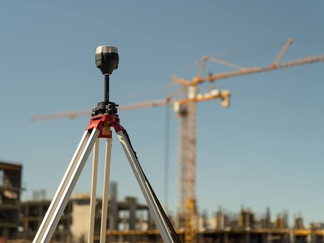
While geodetic surveying accounts for the spherical curvature of the Earth across vast continental and national expanses, the overwhelming majority of day-to-day land development, residential construction, municipal mapping, and civil engineering projects relies on plane surveying. Plane surveying is defined by a deliberate, mathematically justified simplification: it treats the portion of the Earth’s surface under investigation as a flat, two-dimensional horizontal plane, assuming that all plumb lines (the directions of gravity) across the project area are perfectly parallel to one another.
The Mathematical Justification for the Flat-Earth Assumption
At first glance, ignoring the Earth’s curvature might seem crude for a technical discipline obsessed with millimeter-level precision. However, simple spherical geometry demonstrates why plane surveying works reliably within well-defined geographic limits.
Because the Earth has a mean radius of approximately 6,371 kilometers, its surface curves away from a horizontal tangent plane by roughly 7.85 centimeters over a distance of 1 kilometer, or about 8 inches over 1 mile. In terms of horizontal arc-to-chord differences, a line measuring 18.5 kilometers along the curved surface differs from the straight Euclidean chord connecting its endpoints by only about 1.5 millimeters. Similarly, the sum of the interior angles of a spherical triangle on the Earth’s surface exceeds 180 degrees by only 1 arcsecond for every 197 square kilometers of area—a phenomenon known in geodesy as spherical excess.
Consequently, surveying standards generally establish an upper threshold of roughly 250 square kilometers (about 100 square miles) for plane surveying. Within this spatial boundary, differences between planar Euclidean geometry and spherical or ellipsoidal trigonometry fall well below practical field measurement tolerances. This allows surveyors to use straightforward plane trigonometry, Cartesian coordinate systems, and standard bearings without complicated ellipsoidal reduction calculations.
Core Principles and Operations in Plane Surveying
Plane surveying divides field measurement tasks into two primary categories: horizontal control (planimetry) and vertical control (leveling). These are executed through four classic operational techniques:
- Traversing: A traverse consists of a sequence of connected straight lines (legs) whose lengths and interior or deflection angles are measured sequentially. A closed traverse either loops back to its starting station or closes between two known control points, providing an immediate mathematical check on angular closure and linear misclosure.
- Triangulation and Trilateration: Before Electronic Distance Measurement (EDM) became standard, surveyors measured a single baseline accurately and determined the positions of distant points by measuring angles across interconnected triangles (triangulation). Today, modern total stations measure all three sides of triangles directly using infrared lasers (trilateration) or combine angles and distances simultaneously (triangulateration) for maximum geometric strength.
- Differential Leveling: Even in plane surveying, vertical measurements must respect gravity—water flows along equipotential level surfaces, not along an arbitrary tilted plane. Using an optical automatic level or a digital barcode level sighted onto a graduated vertical rod, surveyors carry elevations forward through alternating backsight and foresight readings, naturally canceling out Earth curvature and atmospheric refraction over balanced sight lengths.
- Radiation and Side-Shots: Once primary control stations are established via traversing, the surveyor occupies a control point, sights a backsight for angular orientation, and radiates hundreds of rapid distance-and-angle measurements (“side-shots”) to map curb lines, building corners, utility structures, and terrain contours.
Standard Coordinate Systems: Northing and Easting
In plane surveying, positions are expressed in a local or projected planar Cartesian coordinate system using Northing ( ) along the vertical -axis and Easting ( ) along the horizontal -axis. Directions are defined either as azimuths (angles measured clockwise from 0° to 360° starting from North) or quadrant bearings (acute angles measured from North or South toward East or West, such as ).
Using basic trigonometric formulas:
where is horizontal distance and is azimuth, plane surveyors compute coordinates rapidly in the field and verify parcel area calculations using the coordinate (shoelace) method.
Everyday Applications of Plane Surveying
Because of its speed, clarity, and direct compatibility with standard architectural and civil Computer-Aided Design (CAD) software, plane surveying powers almost all localized built-environment workflows:
- Residential and Commercial Lot Surveys: Delineating parcel corners, verifying building setbacks, and preparing plot plans required for municipal building permits.
- Small-Scale Subdivision Design: Laying out internal street centerlines, cul-de-sacs, stormwater swales, and utility easements across parcels ranging from a single acre to several hundred acres.
- Site Grading and Drainage Plans: Ensuring parking lots, athletic fields, and building pads maintain positive drainage slopes (typically 1% to 2%) away from foundations without requiring geodetic curvature corrections.
- Bridge and Building Layout: Establishing orthogonal column grids on construction sites where local structural axes align with building walls rather than true geodetic north.